
How Is a River Crossing Built? HDD Pipeline Crossings Step by Step
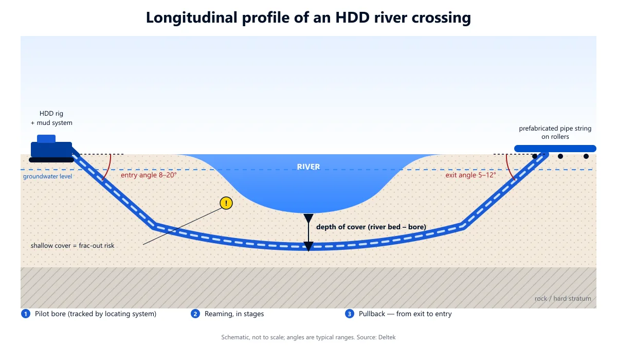
When a pipeline has to cross a watercourse there are three options: hang it on a bridge, dredge the river bed and bury it, or drill underneath the river. The first two touch the water and the banks; the third does not. That is why river crossings for gas, oil, water and cable lines are today built largely by horizontal directional drilling (HDD). This article follows a river crossing from planning to pullback.
Why is a river crossing a subject of its own?
Compared with an ordinary road crossing, three things get harder at once:
- The ground is saturated. The water table is close to the surface, bank fills are loose and the river bed is usually sand, gravel or alluvium. All of these make it harder to keep the bore wall standing.
- Cover is limited. The bore has to pass deep enough below the river bed; if it runs shallow, drilling fluid escapes through the bed into the water.
- The crossing is long. Not only the river width but the ramps on both sides are part of the bore; for a two-hundred-metre river the drilled length easily grows to several times that.
1. Investigation: knowing the river and what lies beneath
Every river crossing starts at the desk. The first step is the geotechnical investigation: boreholes on both banks and, where possible, in the river identify the strata, water table, depth to rock and soil classes. In a river crossing it matters that boreholes are drilled a few metres to the side of the alignment, not on it; otherwise each borehole becomes a ready-made channel for drilling fluid to reach the surface later.
A hydrographic survey is added: the cross-section of the river bed, depth, flow velocity and how much the bed may scour seasonally (scour depth). Depth of cover is calculated not to today’s bed but to the bed that could form in the worst flood.
Finally, existing utilities, embankments and flood defences on the banks are mapped; entry and exit points are chosen where they will not be harmed.
2. Profile design: angles, radius, depth
With the investigation data the longitudinal profile of the crossing is drawn. It consists of three parts: the entry ramp, the horizontal section under the river and the exit ramp.
- Entry angle is typically 8–20°. A steep angle shortens the bore but demands a tighter curve during pullback.
- Exit angle is flatter, usually 5–12°; the pipe string enters the bore at this angle, so the flatter it is the less the pipe is stressed.
- Bend radius depends on pipe diameter and material. In steel pipe the radius must not take the pipe beyond its elastic limit; in practice a lower bound proportional to pipe diameter in inches is used. A smaller radius stresses both pipe and drill rods.
- Depth of cover is the distance between the lowest expected river bed level and the top of the bore. Shallow cover leads to frac-out; unnecessarily deep cover leads to long, expensive ramps. Ground type sets the right balance.
Once the profile is finished, the pipe string lay-down area must also be planned: on the exit side, a straight, unobstructed corridor as long as the pipe is needed. Without it the pipe is pulled in sections and the operation stops for every joint; a single string is preferred wherever possible.
3. Managing frac-out (inadvertent returns)
The most discussed risk of a river crossing is drilling fluid escaping to the surface, that is, into the river. When fluid pressure inside the bore exceeds what the overlying ground can carry, the ground fractures and fluid finds the weakest path upward. Bentonite is not toxic, but it causes turbidity and has serious consequences under environmental regulations.
The risk is managed in three places:
- In design: the upper limit of downhole pressure is calculated at every point; near the banks, where cover is thinnest, the limit is lowest. If necessary the profile is deepened or the bank section is protected with casing.
- In the fluid: flow rate and viscosity are matched to the ground; in loose bank fill, additives that reduce fluid loss are used. The functions of drilling fluid matter once more here.
- On site: fluid pressure and return flow are monitored throughout the bore; falling returns mean fluid is escaping somewhere. The river surface is watched, and a response plan (stop, boom, recovery) is kept ready in advance.
4. Pilot bore
Once the site is set up, the HDD rig, fluid mixing and recycling unit, rod storage and generators are placed on the entry side. The pilot bore is the first and most critical stage, drawing the designed profile into the ground: the steering head is surveyed at every rod and the path corrected against the design profile.
In a river crossing the choice of locating system is decisive here. Walk-over systems require the receiver to walk above the bore path; above a river this is usually impossible or limited to a boat. For long, deep river crossings, wireline (magnetic field) systems that do not depend on the surface are therefore preferred: a current loop laid on the ground serves as reference, and the head position is computed independently of surface access.
5. Reaming
When the pilot bore reaches the exit, the bore is enlarged to suit the pipe diameter. This is done in stages, not in one pass: at each stage a suitable reamer is attached on the exit side and pulled towards the entry. The number of stages is set by the ground; large steps in loose sand cause bore collapse, while in rock they cause tooling wear. In the saturated ground under a river, what keeps the bore open is largely the fluid inside it; uninterrupted fluid circulation during reaming is therefore the rule.
The final bore diameter is generally about one and a half times the pipe outside diameter; the annulus stays filled with fluid and reduces friction during pullback.
6. Preparing the pipe string
While drilling proceeds, the pipe string is prepared on the exit side: for steel pipe, welding and weld inspection, coating repair and pressure testing; for polyethylene, butt fusion and fusion cooling times. The string is placed on rollers so it does not drag on the ground during pullback and is guided into the bore in a curve matching the exit angle.
In large-diameter steel pipe, the empty pipe tries to float in the fluid and rubs against the roof of the bore. To prevent this, water is fed into the pipe in a controlled way during pullback (ballasting): the pipe weight is brought close to the buoyancy of the fluid, and friction and pull force drop.
7. Pullback
In the final stage the pipe string is pulled from exit to entry. At the head of the string sit, in order, the reamer, a swivel that keeps rotation from reaching the pipe, and the pulling head. Pullback is carried out as continuously as possible: with every hour of stoppage, solids in the fluid settle and the pipe starts to stick in the bore. Pull force and fluid pressure are recorded throughout; a force above the expected value is the first sign of trouble.
When the pipe reaches the entry, the crossing is complete. The pipeline’s own tests follow (hydrostatic test and coating check for steel), and the entry and exit pits are closed to restore the banks.
Common mistakes in river crossings
- Calculating depth of cover to today’s river bed; the bed scours in floods and cover thins.
- Drilling investigation boreholes right on the alignment; every borehole is an escape path for fluid.
- Not planning enough straight lay-down length for the pipe string; pulling in sections adds time and risk.
- Not monitoring fluid returns; the first sign of a frac-out is not in the river but in the falling return flow at the entry pit.
- Choosing the locating method without regard to river width and depth.
Deltek’s approach
Deltek is a trenchless contractor carrying out river, highway and railway HDD crossings for BOTAŞ and international pipeline contractors. On river crossings we share in writing at tender stage not only the price but also which method we chose for each of the steps above and why. If you have a watercourse crossing, contact us with your geotechnical report; site survey and feasibility are free of charge.
Get in touch about your project.
0850 888 3585